Highlights :
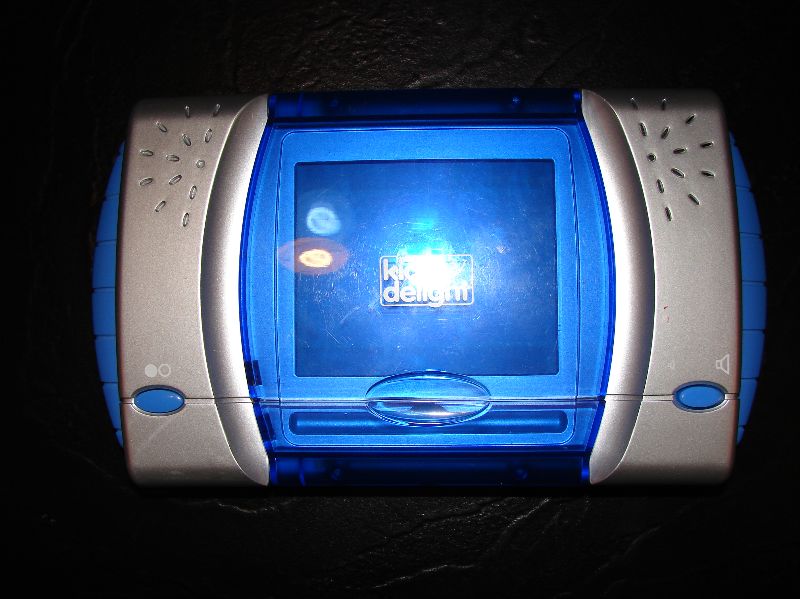
Case – Frankenmoded Datamax Kid’s Delight
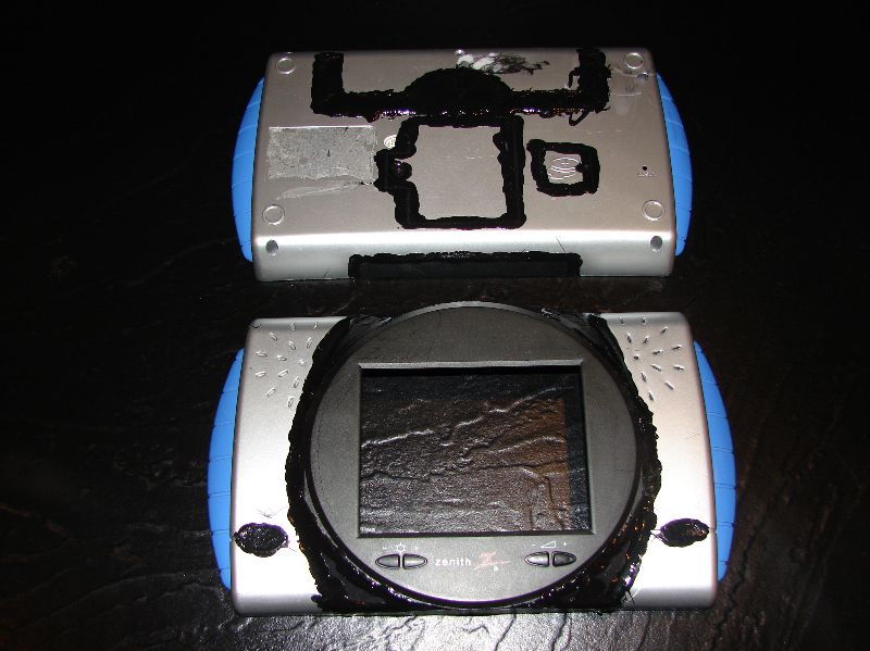
Screen – Unmodded Zenith Psone
Batteries – 14.8v 4700mAh Li-Polys
Controllers – Gamecube, Mini Gamecube, Wii Classic 3rd Party, Dreamcast Quantam Fighterpad
Notes :
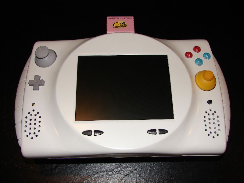
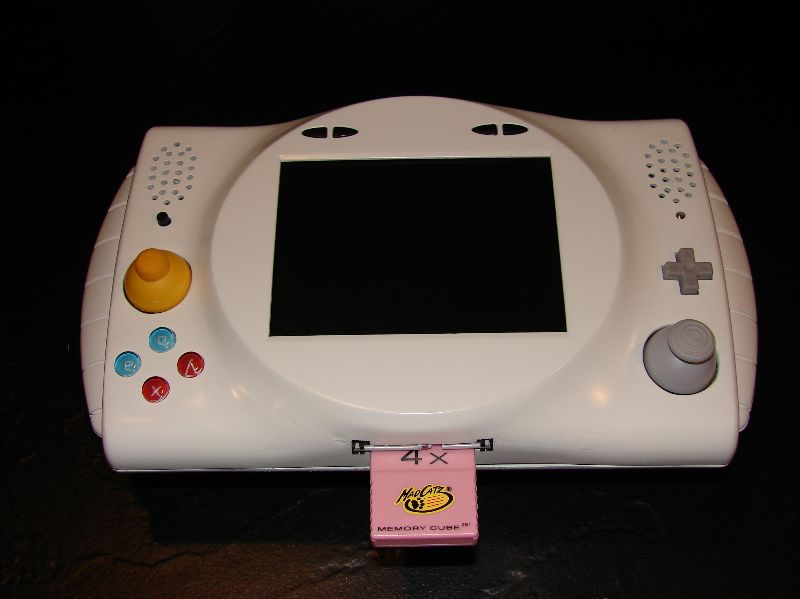
1. Memory card relocated to top.
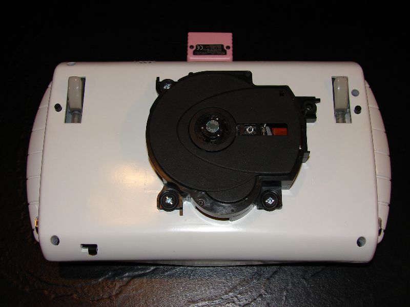
2. Disc Drive relocated with ffc extensions.
3. 2-way switch for running off batteries or wall.
4. About 90 hours of work more or less.
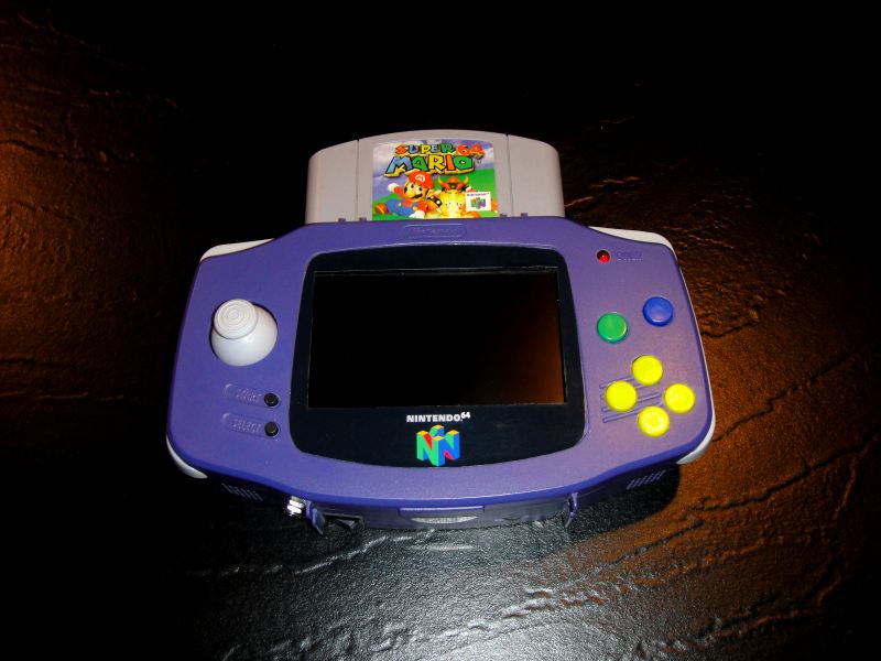
Well here it is :
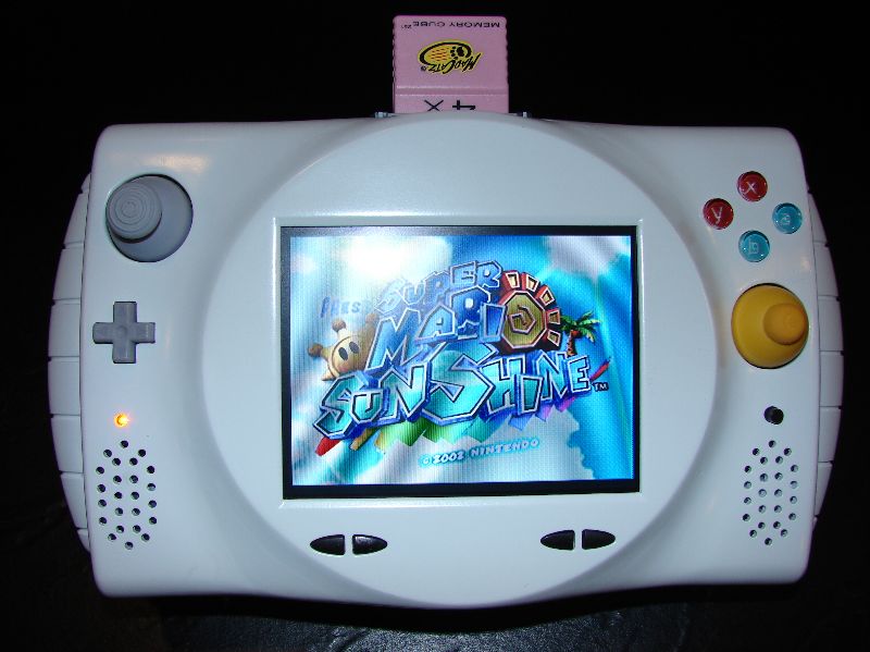
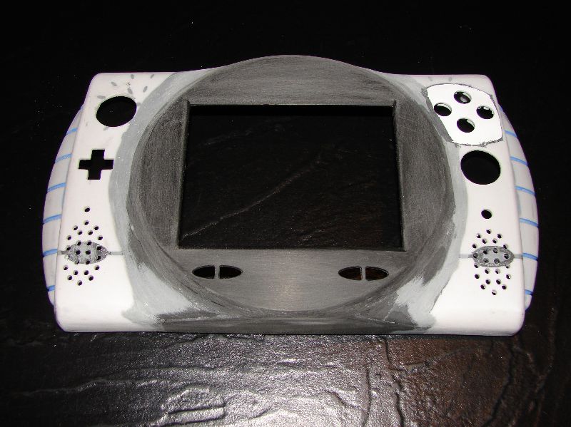
Added a disc cover that I’m not 100% sure I am happy with. I may change it or even paint it.
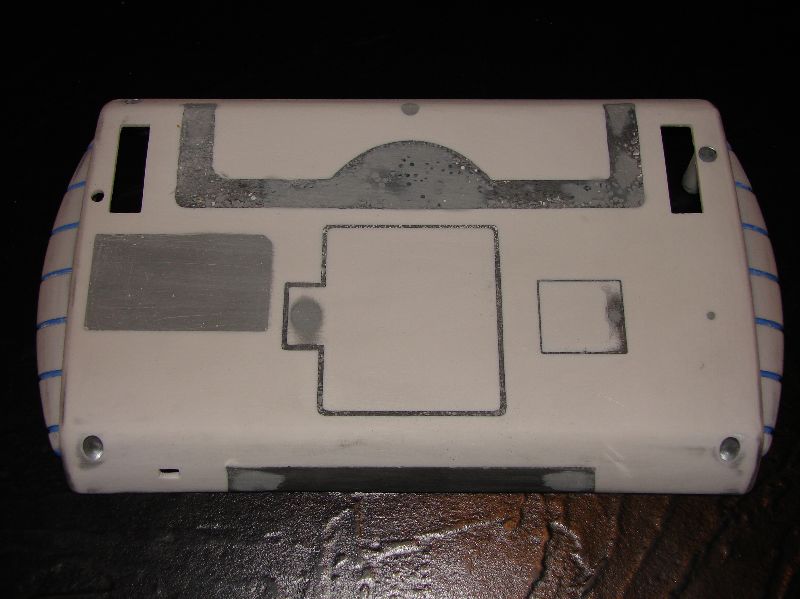
The donor case:
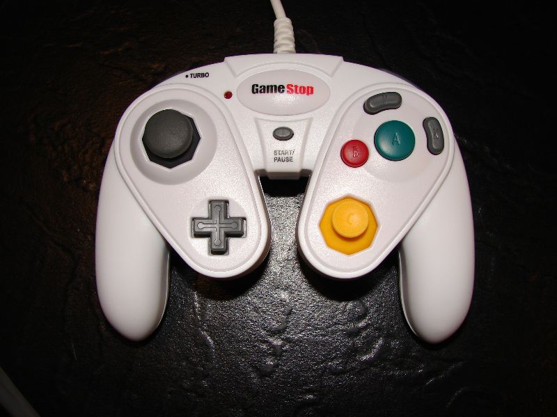
Here is the Gamestop Controller I am using in my GCP :
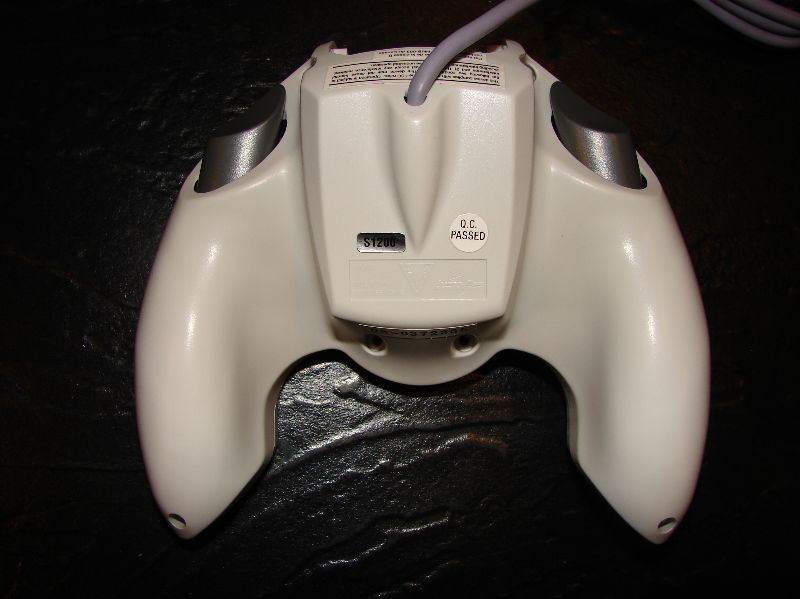
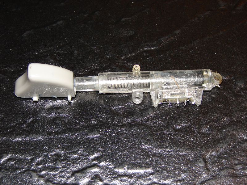
Here is the Quantam Fighter Pad we will be stealing the triggers from:
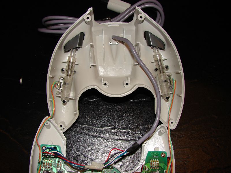
And here are the triggers will be using :
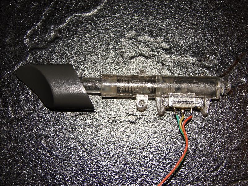
The first thing you do is pull off the old plastic trigger ends from the triggers we took out of the Quantam Fighter Pad. Now take the triggers you stole from a Xbox or Dreamcast controller. Drill a small hole in the end of the triggers. Using hot glue or epoxy fill the trigger with the adhesive of your choice and slide the Quantam Fighter Pad trigger stem into the hole you drilled. Make sure the trigger is facing in the direction you are going to want it facing when you put it in your portable. Allow trigger to set until glue/epoxy hardens. :
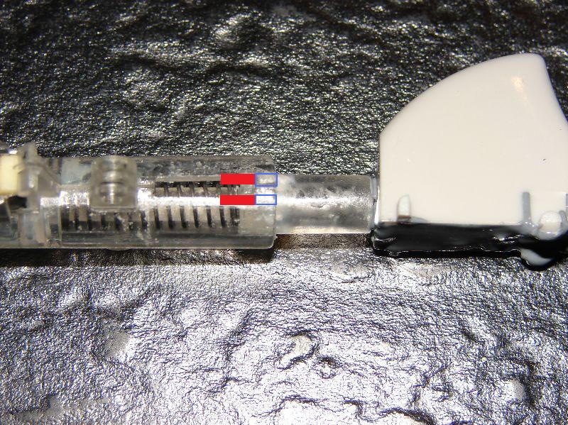
Now you can take the Quantam trigger apart. One screw holds it together and then it just splits apart. When you have it apart you will need to cut the plastic so the new potentiometer from the GameStop controller has more travel. In the pic below you will cut the parts in red off leaving the parts in blue. You can use a razor blade or a file. This will allow the trigger to slide out a bit more.
Now you can desolder the potentiometer from the Gamestop controller. Snip off the 4 corner grounding prongs they will be in the way. And now insert it in the trigger where the old potentiometer was making sure the slider is in the proper orientation. I made sure the slider was all the way out when I desoldered it and then placed it in the new trigger with it all the way out towards the spring so I knew it was facing the right direction.
Now we need to make a button switch to be activated when the trigger is pulled all the way in. For this, we will be using a standard 5mm two-leg tact switch.
You will need to file off the 4 corners of the tact switch to round it off to fit in the new triggers we are making.
After you have rounded it off then put it in the trigger. You will want the silver part of the tact switch to be right above the silver part on the end of the potentiometer.
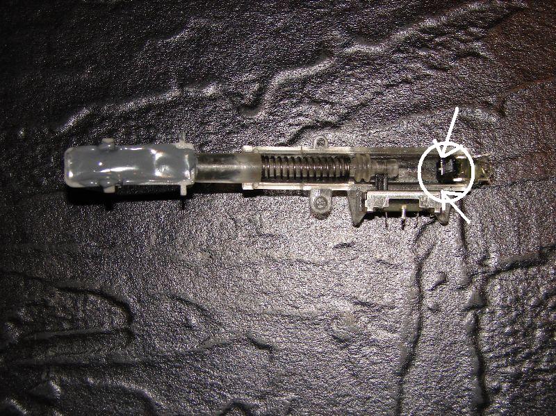
Now using a small amount of hot glue make sure that tact switch stays there.
Now put the trigger back together and you are done. You should be able to get the two halves back together with the legs of the tact switch sticking out, but you might need to make a tiny slot for the legs with a file or a soldering iron.
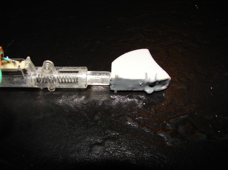
And here is your final product :
How I extended the Gamecube Optical Drive Cables :
First you will need to buy 4 parts from http://www.digikey.com
1. WM10055-ND – 6″ 12 pin 1.0mm ffc cable
2. WM10218-ND – 6″ 10 pin .5mm ffc cable
3. WM7679CT-ND – 12 pin ffc Zif connector
4. OR740CT-ND – 20 pin ffc Zif connector
Total cost will be around $22 shipped with first class mail.
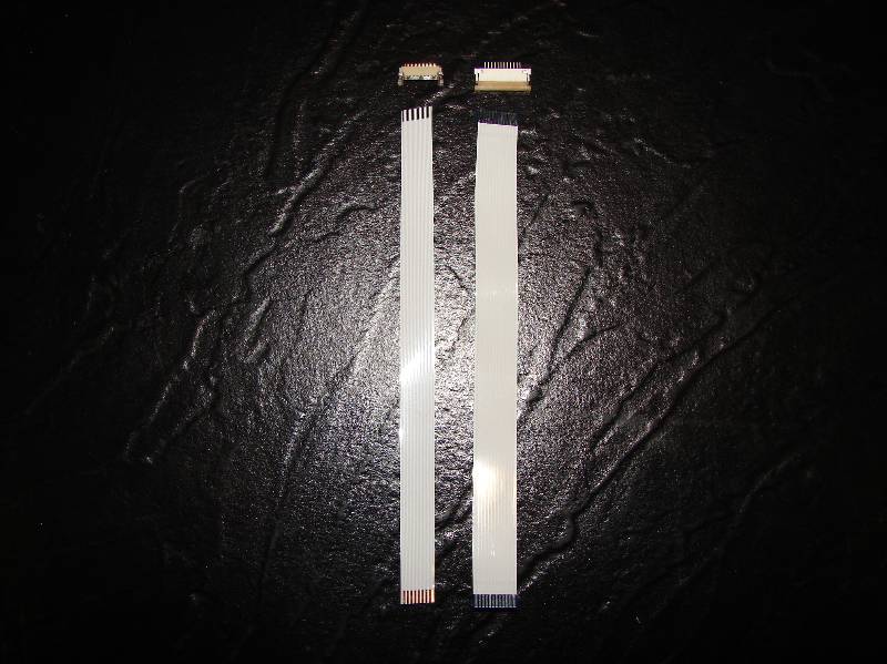
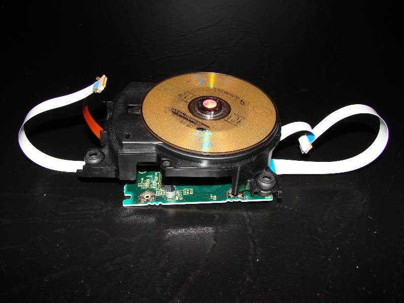
The way this works is by extending the ffc’s (Flat Flexible Cables). These will be the two we are extending. The one on the left is a 20 pin .5mm ffc in a slide lock zif socket. The one on the right is a 12 pin 1.0mm ffc in a no lock socket. :
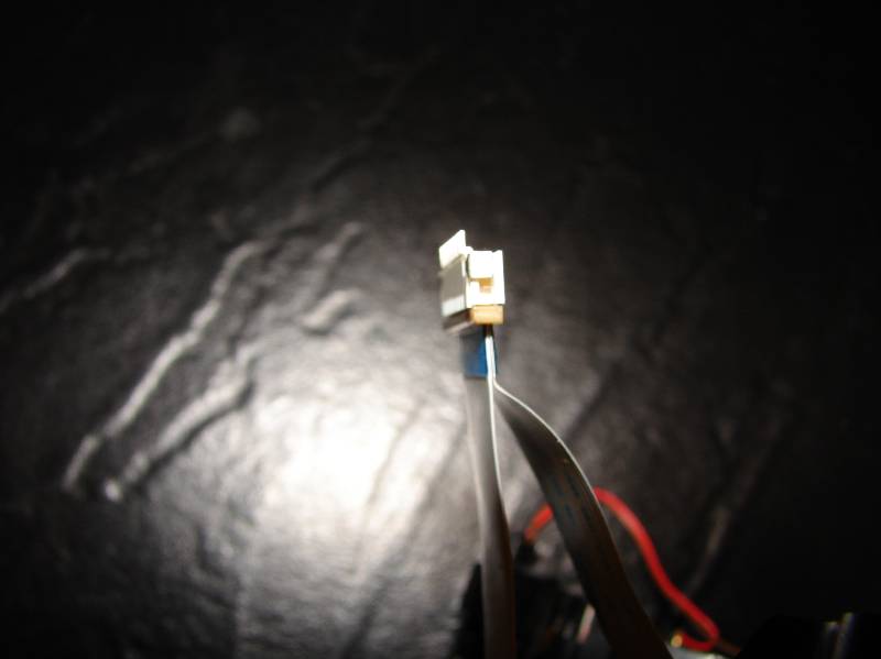
Open the little brown clamp on the zif connector from Digikey. They are pull-out slide lock connectors. Be careful you do want to pull it out too far and break it.
Put the cable you want to extend, and the cable that you bought, face to face so that the silver contacts are touching. Make sure that they are aligned together perfectly, edge to edge , equal length:
Put both cables in the zif and clamp the zif clamp back down. (It may be a little
hard to get them both in there but you can do it. Make sure they are perfectly aligned.)
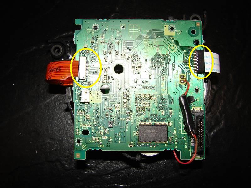
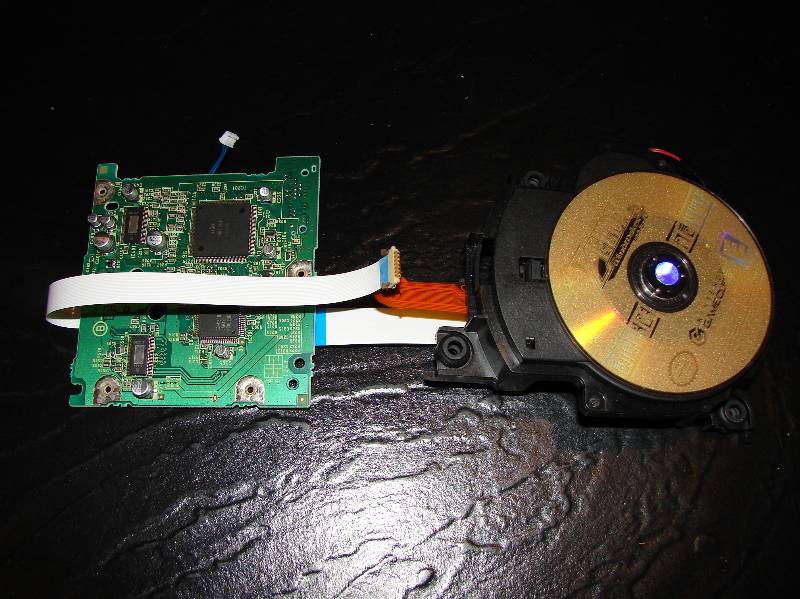
Plug the newly extended cable into the zif on the circuit board. Mind the orientation of the cable (pins); it should be the same as the original cable. On the 20 pin slide in the ffc and then lock the zif socket tab. On the 12 pin just slide in the ffc snugly.
Now notice how much room you have to move the optical drive around :
Now after once again checking to make sure the ffc’s are aligned properly, plug the unit back in and test it. If the ffc’s aren’t aligned you of course will have problems like the optical drive not starting the game or the Gamecube not starting up. Simply turn off the Gamecube and then realign the ffc’s and insert them in the zif sockets again. Mine worked the first time because the way the sockets and ffc’s are designed it’s nearly impossible to get them in NOT aligned properly. There’s just not enough room.
Once you make sure everything is working properly, hot glue the ffc’s and zif socket extensions you made to keep them from pulling loose or shorting out. I also electrical tape mine after hot gluing them for added security.